
During the daily device driver development routine, we often need to understand the behavior of the GPIO pins to understand if there is I2C traffic or if our driver is handling the coming interrupts and so on.
Sometimes is not enough to mount the debugfs interfaces and read out the values or cat/grep the /proc/interrupts file because we may loose the instant when the GPIO changes its status or perhaps we need to keep different terminals open.
Having the possibility to immediately visualize the GPIO status using an LED could be of great help.
The LED is a diod that when stimulated with a current emits light.
The first instict could be to connect the LED directly to the GPIO pin:
If we try we would be disappointed by noticing that the LED emits a weak light, such that we may need to be in complete darkness to understand whether the GPIO is high or low. In any case, depending on the internal resistence of the LED, we risk to short circuit the GPIO pin affecting his behavior.
For having a more secure and efficient circuit, we should keep the GPIO pin as far as possible from the ground and use it just as enabler for switching on and off the PIN. For doing this we need to use a transistor that is controlled by the pin we want to debug.

The circuit above shows how to enable a transistor with the GPIO pin keeping it away from the ground. The 3.3V power source represents the GPIO voltage and is connected to the base of an npn transistor through a 2.2kΩ resistor. When GPIO is high the transistor is active and connects the LED pin to ground so that it emits light. While when 0 the transistor behaves as an open circuit so that the pin of the LED is not connected anywhere and the LED is disabled.
The R2 resistor is needed to disconnect the GPIO from all the parassitic capcitance of the transistor that may affect the frequency on the pin itself. Anyway the transistor needs low voltage to be enabled.
The R1 resistor is optional, needed to not overcharge the LED. Remember that higher is the value of the resistor and lower will be the LED's light.
Bill of materials:
Let's move now to apply our small simple circuit to a real case and let's assume we want to debug the behavior of a GPIO pin of the Raspberry Pi. Let's be equipped of the above components and a breadboard and of course our Raspberry Pi.
This is the Raspberry Pi pinout:
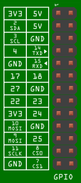
Raspberry Pi provides two pins where is possible to get the 5V we need to enable our LED. Let's say we want to debug GPIO 22 which is connected to the pin 15. By using the schematic we did previously, the connections should be done as follow:

Is the same logic we saw before: the led switches on and off based on the value of the pin 15.
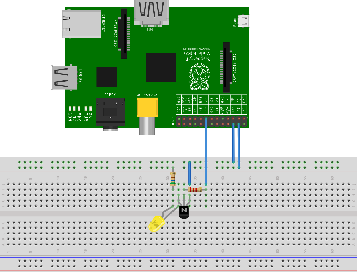
This is an example on how to connect all the components using a breadboard:
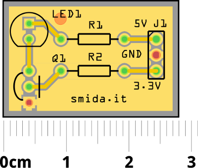
Why stopping here? We can move a bit forward with the imagination and think about printing a PCB for having a more handy solution:
All the pictures and schematics are done with Fritzing
A special thank to my dad who helped me to design this circuit.